Before edge blending can occur, the projectors and software application need to be set-up so that an overlapping region between the edges of adjacent projectors is present.
In this overlapping area, edge blending is later applied. Three steps are required in order to produce an overlap region:
- Calculate the overlap region.
- Align the projectors to the calculated overlap.
- Modify the software application to have the same calculated overlap region.
Calculate the overlap region
As an example, here we present overlapping regions based upon a three projector setup. Each projector has a resolution of 1280×1024 (SXGA).
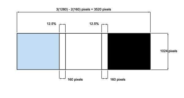 Figure 1: Example overlapping regions of 3 SXGA displays.
Note: It is good to have a complete number of pixels and the same physical screen size when edge blending. However, because of different projector resolutions, it is good to standardize on the same overlapping region.
In this example we use a 12.5% region because existing resolutions result in whole pixels:
- XGA = 1024 * 0.125 = 128 pixels
- SXGA = 1280 * 0.125 = 160 pixels
- SXGA+ = 1400 * 0.125 = 175 pixels
- 720p = 1280 * 0.125 = 160 pixels
- 1080p = 1920 * 0.125 = 240 pixels
In the example described, the total available resolution of the three projectors titled horizontally before overlapping is:
- 3 x 1280 = 3840 x 1024 pixels
Taking our 12.5% overlap region, this equates to 160 pixels with our SXGA projectors (1280 x 0.125 = 160 pixels). As we have two overlapping regions between our three projectors (as shown in Figure 1), our overall displayed resolution will be:
- 3 x 1280 – 2(160) = 3520 x 1024 pixels
Once the overlapping regions have been calculated, we can then align the projectors and software.
Align the projectors to produce the calculated overlap
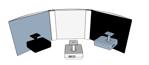 Figure 2: Projector layout with overlapping regions.
The exact layout of the projectors will change depending upon screen size, screen shape and the optics of specific projectors used. Here for illustrative purposes, we show an example of projector placement on a curved screen with the overlapping regions described above.
Once the projectors are aligned, overlapped and ready to go, the software then has to be adjusted to provide the same overlapping regions.
Modify the software application to have the same calculated overlap region
Below we show an image before and after overlap regions are implemented. Figure 3 shows the original image and Figure 4 shows the overlap regions created to correspond to the same regions as described in Figure 1.
 Figure 3: Original software image.
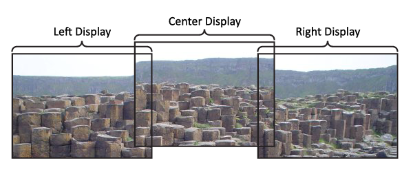 Figure 4: Software setup to produce overlapped regions.
Note: It is worth noting that some applications won’t support overlaps as a standard function.
Due to the number of different software applications available, it is beyond the scope of this section to describe how to perform this function for each possible method. However, if you have any further questions, please contact us.
Once the overlap regions have been created, the next step is edge blending.
Download Resource