Image warping (geometric correction) is used to make an image look visually correct when it is projected onto a non-planar screen.
Image warping (geometric correction) is used to make an image look visually correct when it is projected onto a non-planar screen. This process is also referred to as distortion correction or geometric correction. The image is warped so when it is projected onto the screen it is visually correct.
Forms of image warping can be found in many projector models, with a function known as keystone correction being the most common. Keystone correction (trapezoidal in nature) is used when projectors have been mounted at an angle (generally pointing down from a ceiling to a screen), and the opposing angular correction needs to be applied in order for the image to be correct. Whilst most current projectors offer this feature, in many areas, advanced functions are required. For example, advanced off-axis correction and projection on curved and other unusual surfaces. For these applications, geometric correction tools such as ImmersaView Warp can be used.
Areas where geometric correction is required include:
- Advanced off-axis correction where projector placement is awkward and needs an advanced mapping over the keystone function in a projector
- Non-planar screens such a curved screens and hemispherical domes
- Projecting one image from one projector onto more than one surface
- Unusual projection applications onto custom designed screens
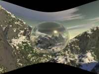
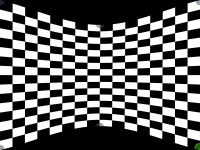 Figure 1: An example of a cylindrical correction.
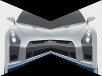
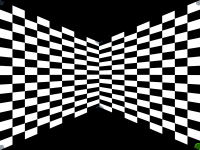 Figure 2: An example of a linear correction onto two planar walls.
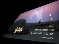
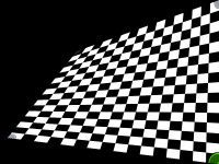 Figure 3: An example of an advanced off-axis correction.
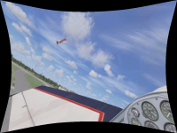
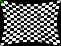 Figure 4: An example of spherical correction.
To describe the process of geometric correction in greater detail, we have taken the example of projecting onto a curved surface. For cylindrical and spherical screens, variations of barrel and pincushion correction functions are required to correct the image. The exact mapping will be dependent upon the optical characteristics of the projector, the screen’s size and shape as well as whether the imagery is front or rear projected.
Geometric correction can be performed with some special high-end projectors with advanced modules, but they are not common and tend to be expensive. There are also external electronic devices which can compensate for any geometric correction, but these also tend to be expensive.
Recently with advances in computer graphics cards, software solutions can now offer the ability to perform geometric correction. One such tool is ImmersaView Warp. This method provides a user with a number of control points which can be increased/decreased depending upon the complexity of the screen shape (see Figure 5). These control points can be manipulated by the user so an image is aligned correctly to a screen.
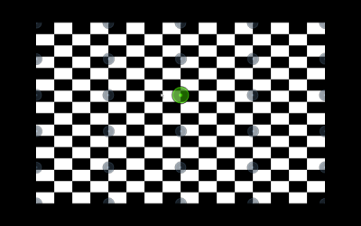 Figure 5: Control points for included for image warping.
Typically, when a standard projector is used on a curved (cylindrical) screen, the image gets a characteristic “smile” shape (see Figure 6). To overcome this we need to use the control points along the top and bottom of the image to pull the image back down into shape. Because the pixels in the middle of the image will be bigger than the pixels at the edges, we compensate for this by dragging the control points near the center of the screen closer together. This tells the software system that these parts of the screen are further away and it automatically adjusts. ImmersaView Warp displays a checkerboard, which helps to create the right image warping pattern. When all the checks in the checkerboard look the same size, the distortion correction is correct.
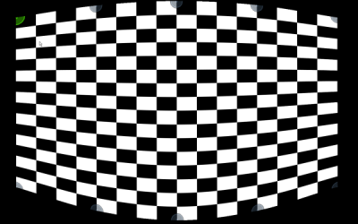 Figure 6: Characteristic smile distortion when projecting onto a cylindrical screen.
There are also other screen shapes that can be produced from complex curved and flat sections. One example of a linear based display is a wedge, composed from two flat screens. Here a single projector can be used with two advanced keystone correction patterns to project onto a single screen. Figure 7 shows an example of the pattern needed to rear project onto a convex wedge screen. To create these shapes the distortion systems need to be told that they are dealing with flat sections and rather than curved screens.
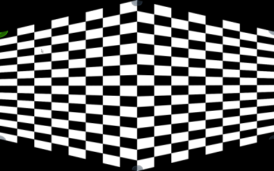 Figure 7: Projection map onto a two linear screens from one projector.
 Download Resource