Multi-channel display set-ups are used when more than one projector is needed in a display system.
This may be because an increased field of view or a higher resolution displays than that offered by a single projector is required. There are a number of areas which need to be considered when undertaking a multi-channel display including how the displays settings are configured on the PC, the field of view (FoV) of the display device and how the software is configured to match the display’s FoV.
Display Settings
There are a large number of possible display set-ups available which can be provided natively by the operating system or with additional options provided with display drivers and external devices. We don’t intend to describe all of these alternative modes, but we do highlight a number of common uses for illustrate purpose.
Single Display
To set-up a display for a single projector, this can be done by opening the display properties on a Windows PC and using the slide bar to adjust the resolution to the required setting. We recommend using the native resolution of the projection device when setting up display resolution. For example, a SXGA projector would be set to a resolution of 1280×1024 pixels.
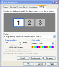 Figure 1: Single display with a single output.
Multi Displays
With current graphics cards and mother boards, it is possible to set-up a number of outputs from one PC. Figure 2 shows three active outputs, each set to a resolution of 1280×1024 pixels which are horizontally configured.
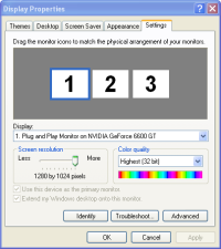 Figure 2: Three individual displays with three outputs.
Horizontal Span
Figure 3 shows the “horizontal span” mode which is provided in the NVIDIA driver settings (and with a similar setting available on the ATI drivers). Here, displays [1] and [2] as shown in Figure 2 are combined into one large horizontal display. Display [1] is now seen as one individual display, with a total resolution of 2560×1024 pixels (2x 1280×1024).
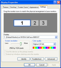 Figure 3: Single display in horizontal span with two outputs.
External Display Modules (Matrox)
In addition to standard graphics cards and specific drivers, there are also external expansion modules which can be added to graphics cards. One such company providing these solutions is Matrox Graphics Inc. These devices enable one graphics card to have an extended desktop over 2 or 3 output devices.
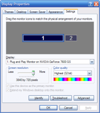 Figure 4: Single display using a Matrox “Triple Head to Go” adaptor with three outputs.
Multi-PC displays
Figure 5: Single display output on two PCs providing two outputs.
Figure 5 shows the same display and resolution settings from two different PCs. Here one PC provides the graphics for one projector. Any number of PCs and projectors can be combined in this instance to meet various display requirements. For this type of set-up (often referred to as a PC cluster) the software has to know that there are others PCs in the system and also which PC is rendering which part of the scene. This is commonly referred to as the display channel’s FoV.
Display FoV
Generally curved screen displays are defined in terms of it’s field of view. Here, we describe a curved screen set-up using 3 projectors to produce a display of 160 degrees horizontally and 40 degrees vertically.
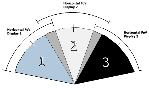 Figure 6: 3 Projector set-up with overlaps producing a 160×40 degree display.
Figure 6 shows the horizontal FoV for 3 projectors used in a curved screen set-up. The diagram also shows an overlapping region between display 1 and 2, and between 2 and 3. This overlapping region is used for edge blending to produce a seamless image.
The specifications for the display are as follows:
- Overall horizontal FoV = 160 degrees
- Overlap region FoV = 5 degrees (10 degree total)
- Required overall FoV to be generated = 170 degrees (160 + 10)
This therefore results in a horizontal FoV (HFoV) for each projector of 56.67 degrees (170/3). The heading information (i.e. the position of the centre of each projector) as defined by a black line in centre of each projector in Figure 6, is 53.33 degrees (160/3).
This results in the following information:
| Display 1 | Display 2 | Display 3 | |
| Heading | -53.33 | 0 | +53.33 |
| HFoV | 56.67 | 56.67 | 56.67 |
| VFoV | 40.00 | 40.00 | 40.00 |
This information can then be used in the software application to define each field of view.
Software
Many software programs treat display environments in a number of ways, so we only describe possible set-ups from a high level view in this document. We do not present how particular settings are configured in particular software applications, so please reference the relevant software vendor’s documentation for further details.
To begin, it is important to understand the FoV requirements of the display. Above we describe a display with a 160 HFoV by 40 VFoV using three projectors. The FoV information and heading information can then be added to the software program to ensure the visuals generated by the software application, match the visual requirements of the screen.
This information can be rendered by the software application and graphics card in many of the display mode mentioned above, either as multiple graphics out from a single PC, or as separate information from a number of PCs. When a number of PCs are used, the software has to be aware of other external nodes and generally this is configured by the software using a network protocol.
Download Resource